




Key Takeaways
- One integrated cell replaces six manual steps — slitting, cutting, screening, discharging, mold tilting and takeout — feeding a 200T-300T vacuum press at 10-15 pcs/min.
- Per-piece weight accuracy of 0.1g and feeding accuracy of 0.1mm make the blank a molding quality parameter, not just a cutting result.
- Two integration architectures exist: mold-side XCJ-600# (600mm cut width, 3.8kW, 1000kg) and calender-fed XCJ-FQTL-470 (470mm roll, 4.3kW, up to 200 cuts/min, 680kg).
- The layout envelope of 540mm x 600mm and switchable arrangement schemes let one operator run multiple presses from a single HMI.
Most rubber plants already own a cutter. What they lose hours to is everything around it: people slitting strip, carrying blanks, screening weights, tilting molds and pulling hot parts out. The automatic cutting and feeding machine deletes exactly that segment of the workflow.
This guide covers what the integration replaces, why blank weight tolerance belongs to molding, the two architectures, a five-step cycle, and the layout and diagnostics that decide success on your floor.
What Does the Workflow Integration Actually Replace?
On a conventional line, the high-temperature vulcanization process depends on a chain of manual tasks: slitting, cutting, screening, discharging, mold tilting and product takeout. Each handoff adds handling time and a chance for error, because every transfer of a hot, tacky blank is a measurement done by a person. The integrated machine takes over all six steps in one cell, with real-time cutting and display so each blank’s weight is known before it reaches the mold.
The second effect is invisible on a layout drawing. Because the cell feeds the press automatically, personnel stop standing next to a 150-plus °C station for an entire shift — the same heat-exposure concern that OSHA flags for hot work environments (OSHA heat exposure guidance). Labor moves from a hazard zone to a supervision position, and quality becomes repeatable because blanks are placed with 0.1mm feeding accuracy instead of by eye.
Why Per-Piece Weight Tolerance Is a Molding Parameter, Not a Cutting Parameter
Buying decisions usually compare cutting speed, but the number that decides part quality is blank weight tolerance. Flash thickness, short shots and cavity pressure are all downstream consequences of blank weight, because the mold only closes around what it is given. A blank 5-10% overweight vents its surplus through the parting line as flash; a blank 5% underweight risks voids and undersized parts. Typical values from our experience mapping weight deviation to molding outcomes:
| Blank weight vs target | Effect inside the mold | Downstream consequence |
|---|---|---|
| +5% to +10% | Cavity overfilled; surplus escapes the parting line | Heavy flash; deflashing load rises sharply |
| +1% to +5% | Flash concentrated on parting line only | Moderate trimming needed |
| ±1% or tighter | Flash held inside tolerance band | Consistent parts, stable cycle |
| −1% to −5% | Short-shot risk; incomplete fill | Rework or scrap |
| Below −5% | Voids and undersized sections | Part rejected at inspection |
Outcome bands are typical values from our experience (molded NBR, EPDM and silicone parts); accuracies quoted below are official specifications.
This is why the cell weighs at two levels. The XCJ-600# uses dual-channel, dual weighing sensors to sort every blank against the set tolerance at up to 0.1g maximum weight accuracy. The calender-fed XCJ-FQTL-470 holds weight tolerance to ±0.05 per mille, because its self-heating calender roller controls thickness to ±0.5 per mille before the cut even happens. When weight is controlled before the press closes, flash becomes a designed outcome instead of a daily surprise.
Which Integration Architecture Fits Your Line: XCJ-600# or XCJ-FQTL-470?
Two architectures cover most floors, solving the workflow from different ends. The XCJ-600#-A automatic cutting and feeding machine is a mold-side cell that completes the slitting-to-takeout cycle at the press; the XCJ-FQTL-470 silicone strip cutting and feeding machine is an online calender-fed slitter that connects seamlessly with the vulcanizing machine and eliminates the film-covering and tearing process by feeding calendered strip directly.
| Parameter | XCJ-600# (A/B/C) | XCJ-FQTL-470 |
|---|---|---|
| Architecture | Mold-side cell for 200T-300T vacuum press | Calender-fed online slitter-cutter |
| Max cutting width | 600mm | ≤400mm (calender roll 470mm) |
| Thickness range | Up to 15mm | 1.5-12mm calendered |
| Cutting speed | 10-15 pcs/min | Up to 200 cuts/min (servo) |
| Weight accuracy | 0.1g | ±0.05 per mille; scale 3kg/0.1g |
| Feeding accuracy | 0.1mm | Pressing accuracy ±0.5 per mille |
| Overall power | 3.8kW | Max 4.3kW, AC220V 50Hz |
| Machine size | 2300x1000x2850mm (3300mm total height) | 870x1880x1850mm, operation height 1050mm |
| Weight | 1000kg | 680kg |
| Control | Stepper-motor slitting, dual-sensor weighing | PLC + HMI + servo (LEISAI SC2-C32A6D, LT2370) |
Source: official product pages for the XCJ-600#-A/-B/-C and XCJ-FQTL-470 on xmxcjrubber.com.
The honest trade-off: the XCJ-600# handles slabs up to 15mm and posts finished parts directly out of the press, while the FQTL-470 wins on cut rate and precision for silicone strip. Within the XCJ-600# family, the XCJ-600#-B and the XCJ-600#-C straight up-and-down variant exist because press geometry differs — on the C the lower mold lifts without removing the main body of the molding machine. Choosing the variant is an interface decision between cell and press, not a power decision.
How the Material Flows: The Five-Step Integrated Cycle
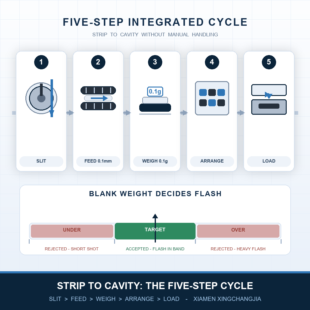
Inside the cell, strip stock travels a fixed path in five steps, and each step corresponds to one mechanism you can see, touch and troubleshoot.
- Slit to width. A stepper motor controls the slitting stroke, while a mechanical torque limiter on the packaging film maintains winding and unwinding tension, so strip never feeds crooked.
- Feed without deformation. The up-and-down synchronous double-belt line increases contact area on the blank, holding position to 0.1mm and avoiding the local roller pressure that deforms soft blanks.
- Weigh and sort. Dual-channel, dual weighing sensors check every blank against the set tolerance; out-of-tolerance pieces are screened out before they reach a mold.
- Arrange and transfer. The arrangement mechanism lays blanks inside a 540mm x 600mm envelope, and the layout scheme switches freely per product or mold.
- Load and reclaim. Blanks enter the mold of the 200T-300T vacuum machine; after vulcanization, a two-axis-adjusted pneumatic finger with lifting assist retrieves the products, completing the loop.
Where Should the Machine Sit, and What Can Go Wrong?
Layout is where integration projects quietly fail. The XCJ-600# needs roughly 2.3m x 1m plus clearance for the 3300mm total height and mold service, while the FQTL-470 fits into 870mm x 1880mm with a 1050mm operation height beside an existing line. Plan the cell around the mold-opening position, not the wall outlets, because the reclaiming finger must reach the mold center through its full two-axis range. The FQTL-470 runs on standard AC220V 50Hz at max 4.3kW, so most workshops need no three-phase upgrade.
Multi-machine management tip
Typical integrations place one cell between two presses so a single operator covers both during unmanned-batch runs (typical values from our experience). Confirm the arrangement scheme before the batch starts — scheme changes are parameter selections, not mechanical rebuilds.
When output drifts, the symptom usually points back to one mechanism in the five-step path. Any intervention should follow standard guarding practice such as the OSHA machine guarding program, because the cell combines moving belts, a cutting station and a servo calender.
| Problem | Likely cause | Solution |
|---|---|---|
| Blank weight drifts beyond 0.1g | Weighing sensor drift or scale out of calibration | Recalibrate the dual-channel scale against a 0.1g reference |
| Blanks land off-position in the mold | Double-belt tension mismatch or wrong arrangement scheme | Re-sync the upper and lower belts; reload the correct layout scheme |
| Strip feeds crooked or jams | Film winding tension wrong at the limiter | Reset the mechanical torque limiter |
| Flash suddenly heavier after weeks | Calendered thickness crept up (FQTL-470, 1.5-12mm band) | Verify ±0.5 per mille pressing accuracy; re-zero thickness |
Diagnostic pairings are typical values from our experience with installed cells; confirm against your press and compound records.
Conclusion: Buy the Workflow, Not the Machine
An automatic cutting and feeding machine pays for itself in the six handoffs it deletes, because every deleted handoff removes labor minutes and a quality risk. Size the decision on the tolerance chain — 0.1g weight accuracy on the XCJ-600#, ±0.05 per mille on the calender-fed XCJ-FQTL-470 — and on how your press geometry meets the A, B or C variants. If your plant still moves blanks by hand, run the audit above first.
Explore the automatic cutting and feeding machine series, compare the standalone automatic weight cutting machine if full integration is not yet practical, or browse all rubber cutting machines — and send us your mold drawings for a layout proposal within 48 hours.
Related Equipment Information
• Automatic cutting and feeding machine series — all three press-side variants and the calender-fed model.
• XCJ-600#-A automatic cutting and feeding machine — full specifications for the 200T-300T vacuum press cell.
• XCJ-FQTL-470 silicone strip cutting and feeding machine — calender-fed online slitter with ±0.05 per mille weight tolerance.
• Automatic weight cutting machine — the standalone cutter the integrated system builds on.
• Rubber cutting machine category — CNC strip, slitter, gasket and sheet cutting equipment.
Frequently Asked Questions: Automatic Cutting and Feeding Machine Workflow Integration
How is an automatic cutting and feeding machine different from a standalone weight cutting machine?
Which molding presses can it feed?
What materials and dimensions can it handle?
How accurate is the feeding and weighing?
How many operators does one machine replace?
How much floor space does integration require?
Xiamen Xingchangjia Non-Standard Automation Equipment Co., Ltd.
Floor1, Building 13, Huli Industrial Park, Meixidao, Tongan, Xiamen China
Email: info@xcjrubber.com | Website: www.xmxcjrubber.com
Published: November 2026 | Last verified: November 2026
Post time: Nov-17-2026