




Key Takeaways
- A full calibration cycle on the XCJ-A 600 — warm-up, zero check, reference weight, tolerance confirmation and a 20-piece acceptance test — takes 25–35 minutes (typical values from our experience).
- Run a 5-piece weight spot-check at every shift start or material change, and a full sensor calibration every 30 operating days.
- A weighing drift of just 0.5–1.0 g is enough to reject good blanks, because the machine automatically sorts every part into acceptable or unacceptable weight before discharge.
- The XCJ-A 600 handles NBR, FKM, natural rubber and EPDM but excludes silicone — calibrate within those material families only.
The short answer: You calibrate an automatic weight cutting machine by verifying its weighing sensor against a certified reference weight, re-zeroing the system on the Delta touch screen, confirming the tolerance band, and running a 20-piece acceptance test. On the XCJ-A 600, a complete cycle takes 25–35 minutes (typical values from our experience). Because the machine automatically separates acceptable parts from unacceptable ones by weight, calibration is the single procedure that keeps every accept/reject decision trustworthy.
An automatic weight cutting machine looks like a cutting device, but its accuracy actually lives in the weighing chain: the LASCAUX weight sensor, the digital transmitter and the Delta PLC that compares each blank against the tolerance you set on the screen. The cutting width of 550 mm within the 600 mm working surface matters far less than whether a 12 g blank reads 12 g on that day.
This guide walks through the full calibration workflow on the XCJ-A 600 automatic weight cutting machine: what you are really calibrating, a step-by-step procedure, recommended intervals by material, and a drift troubleshooting table. It is written for shop-floor operators and quality engineers, following the traceability principles published by NIST Office of Weights and Measures.
Why Calibration Matters More on a Weight-Based Cutter
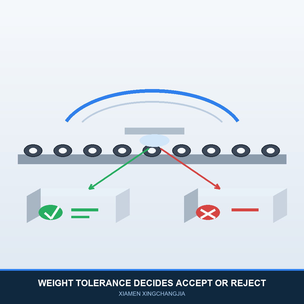
Every cut decision on this machine is a weighing decision. The operator sets the required tolerance range directly on the touch screen, and the machine then automatically separates and weighs each product: parts that fall within the range are classified as acceptable, and parts outside it are labeled unacceptable and diverted. Because that comparison happens automatically and at production speed, an uncalibrated sensor does not just misread one part — it silently mis-sorts an entire shift.
The consequences compound quickly. If the sensor reads 1 g heavy, good blanks near the upper tolerance limit get rejected, and the mold-count logic — set to feed out a fixed quantity per mold, such as 6 or 10 pieces — stops delivering complete counts, because rejected pieces never reach the discharge. As a result, a drift you could correct in 30 minutes instead becomes a shortage your packing team discovers hours later.
What You Are Actually Calibrating: The Weighing Chain
Before touching any parameter, it helps to know which components participate in the weight reading. The XCJ-A 600′s specification sheet lists the exact chain:
| Component | Specification (XCJ-A 600) | Role in Weight Accuracy |
|---|---|---|
| Weight sensor | LASCAUX | Measures each blank; the component that drifts most over time |
| Digital transmitter | LASCAUX | Converts the sensor signal into the digital value shown on screen |
| PLC / touch screen | Delta | Compares the reading against your tolerance band and issues accept/reject |
| Stepper motors | 16 Nm and 8 Nm | Drive the feed and cutting motions; feed consistency affects sample stability |
| Linear guide rail | Japanese THK | Keeps the slider motion smooth, so parts land on the weighing point consistently |
| Pneumatic system | Airtac | Actuates separation; unstable air pressure causes reading scatter |
| Machine footprint | L1270 × W900 × H1770 mm | Must sit level and vibration-free — the foundation of stable readings |
Parameters sourced from the manufacturer’s product page for the XCJ-A 600 automatic weight cutting machine.
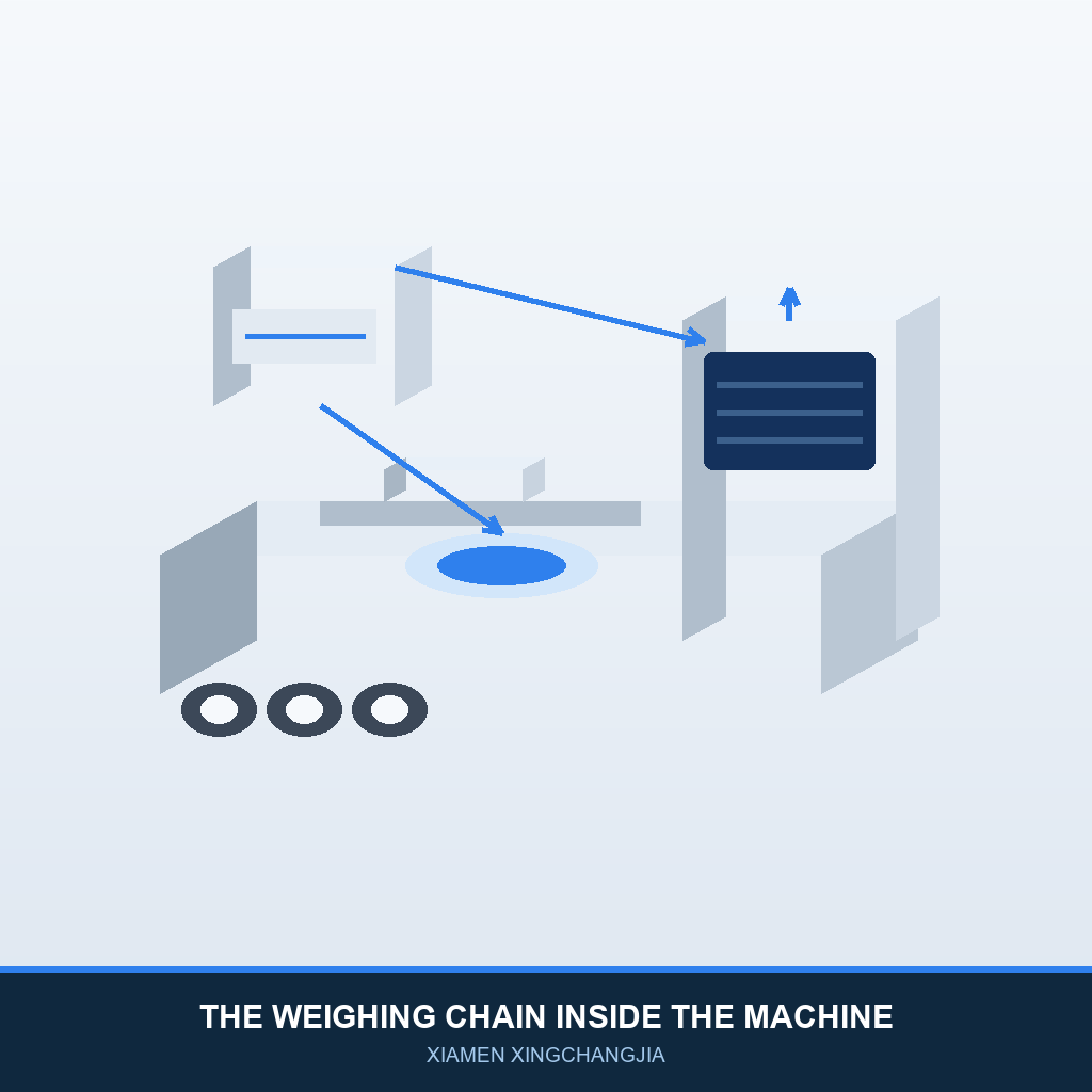
Calibration corrects the sensor-transmitter-PLC chain, not the mechanics. If parts physically jam or feed unevenly, no calibration will fix that — you are looking at a guide rail or air supply issue instead.
Step-by-Step Calibration Procedure
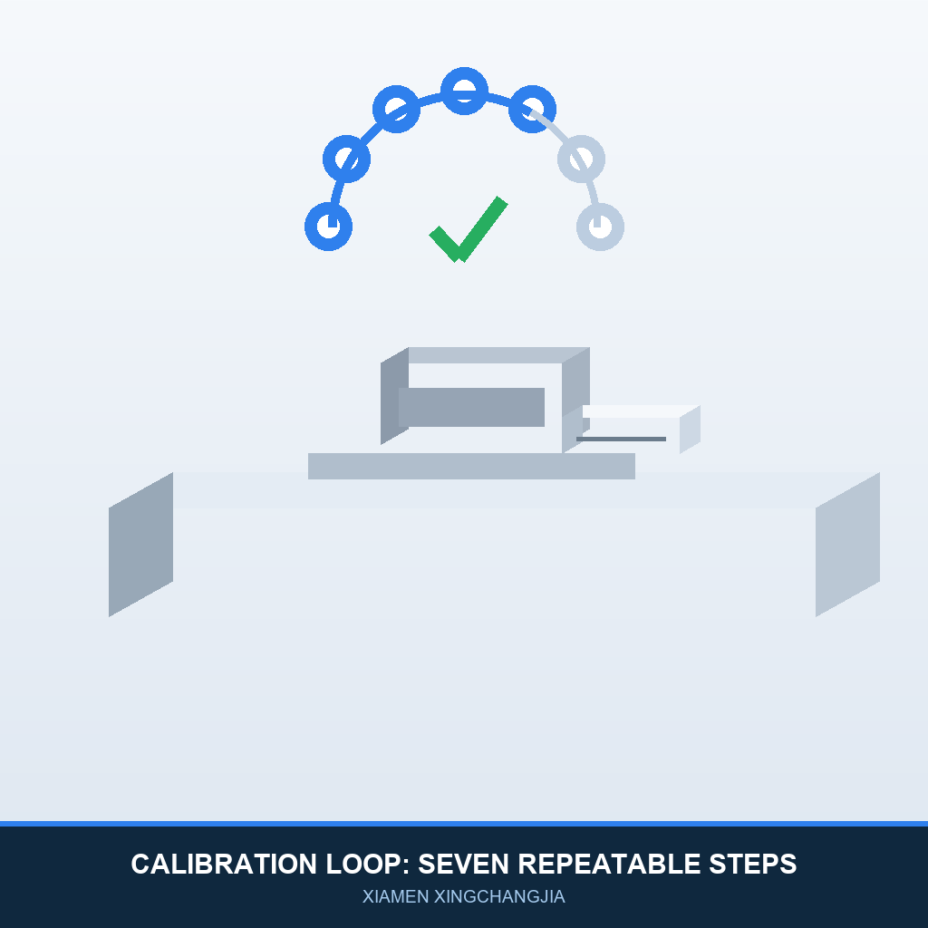
The following sequence assumes the machine is installed level, connected to stable compressed air, and warmed up for at least 15 minutes after power-on. Cold electronics and cold pneumatics are the most common source of false “drift”:
- Warm up and clean. Let the machine run 15 minutes, then wipe the feeding and weighing surfaces clean. Rubber dust and flash residue of just a few tenths of a gram per part distort the reference mass itself.
- Zero the system empty. On the Delta touch screen, trigger the zero function with no part on the weighing point. Confirm the displayed value returns to 0 g and stays there for 30 seconds without flickering.
- Place the certified reference weight. Put a test weight whose mass sits near your typical blank mass (for example 10–50 g, OIML class) on the weighing point and wait for the stable reading.
- Compare and correct. If the reading deviates by more than 0.5 g from the certified value, adjust the transmitter offset per the manufacturer’s instructions, then repeat the zero check from step 2.
- Confirm the tolerance band. Re-enter the required tolerance range on the screen and verify it matches the current part’s specification — compound changes silently invalidate old bands.
- Run a 20-piece acceptance test. Feed 20 blanks of known-good parts through the cycle. All 20 should be classified acceptable; one or more rejections means your band is tighter than real part-to-part variation.
- Record the result. Log date, reference weight value, displayed value, offset applied and test result. A one-page logbook satisfies the measurement-traceability expectations of an ISO 9001 quality system without extra software.
Use a certified part as your second reference
Keep one production blank whose mass was measured on a calibrated lab balance, sealed in a labeled bag. Comparing the machine’s reading against this “golden part” daily catches drift between full calibrations at zero cost.
Calibration Intervals and Tolerance Bands by Material
The XCJ-A 600 processes NBR, FKM, natural rubber and EPDM families (silicone products are excluded by the manufacturer — for those, a dedicated silicone cutting machine is the right tool). Denser compounds and higher hardness generate more cutting vibration and faster sensor scatter, so intervals differ:
| Material | Spot-Check Frequency | Full Calibration Interval | Typical Tolerance Band |
|---|---|---|---|
| NBR | Every 8-hour shift | 30 operating days | ±1.5–2.0 % of target blank mass |
| FKM | Every 8-hour shift | 30 operating days | ±1.5–2.0 % of target blank mass |
| Natural rubber | Every 4 hours | 20 operating days | ±2.0–2.5 % of target blank mass |
| EPDM | Every 4 hours | 20 operating days | ±2.0–2.5 % of target blank mass |
Intervals and bands are typical values from our experience with mid-volume seal and gasket production; adjust after reviewing your own first 90 days of logbook data.
Because natural rubber and EPDM show higher part-to-part mass variation, a tolerance band copied from an NBR job will over-reject on these compounds. Tighten the band only when your acceptance tests prove the process can hold it.
Troubleshooting Calibration Drift
When readings move unexpectedly between calibrations, work through this diagnosis table in order — the causes listed first account for roughly 80 % of field reports (typical values from our experience):
| Problem | Likely Cause | Solution |
|---|---|---|
| Zero flickers ±0.3–0.5 g | Vibration from an unlevel base or a neighboring machine coupled through the floor | Level the L1270 × W900 mm footprint, add vibration pads, relocate the source |
| Stable but consistent offset | Genuine sensor/transmitter drift or residue buildup on the weighing point | Clean, re-zero, then correct the transmitter offset with the reference weight |
| Good parts rejected | Tolerance band tighter than real compound variation, or density change in a new batch | Re-run the 20-piece test; widen the band to match measured variation |
| Readings scatter after jam | Feed disturbance — slider motion interrupted on the THK guide rail | Clear the jam, clean the rail, re-run the acceptance test before production |
| Rejections rise late in shift | Airtac pneumatic pressure sagging as shop air demand peaks | Regulate inlet air to spec; stagger high-demand equipment |
Escalation rule
If two consecutive corrections move the offset in the same direction, stop adjusting and request a sensor inspection. Chasing a drifting sensor with offsets masks a failing component and eventually produces a hard stop mid-shift.
Conclusion: Make Calibration a 30-Minute Habit, Not an Emergency
A calibrated automatic weight cutting machine is a quality gate; an uncalibrated one is a scrap generator with a touch screen. The routine is short — zero check, reference weight, tolerance confirmation, 20-piece test, one logbook line — and it protects the two functions buyers actually depend on: automatic accept/reject weighing and the fixed per-mold count of 6 or 10 pieces.
If you are evaluating weight-based cutting for NBR, FKM, natural rubber or EPDM parts, review the XCJ-A 600 automatic weight cutting machine specification page, browse other machines in the rubber cutting machine category, or pair it with the rubber separator machine category for downstream sorting. Our team answers calibration and application questions in writing before you order — ask us anything.
Related Equipment Information
• XCJ-A 600 Automatic Weight Cutting Machine — full specification sheet for the machine calibrated in this guide.
• Rubber Cutting Machine Category — CNC strip cutting, slitting, gasket and weight-based cutting options.
• Rubber Separator Machine Category — downstream weight- and air-based sorting for deflashed products.
• Silicone Cutting Machine Category — the correct equipment family for silicone products, which the XCJ-A 600 excludes.
Frequently Asked Questions: Weight Cutting Machine Calibration
How often should I calibrate my automatic weight cutting machine?
What test weights do I need for calibration?
Why does my machine reject parts that are within tolerance?
Can I calibrate the XCJ-A 600 for silicone products?
How long does a full calibration take?
Does calibration affect the per-mold quantity setting?
Xiamen Xingchangjia Non-Standard Automation Equipment Co., Ltd.
Floor1, Building 13, Huli Industrial Park, Meixidao, Tongan, Xiamen China
Email: info@xcjrubber.com | Website: www.xmxcjrubber.com
Published: September 2026 | Last verified: September 2026
Post time: Sep-28-2026